Define Viewpoints in Render Mode
The concept of a viewpoint can also be applied in Render Mode. This is great for presentation and has the added bonus of being able to switch display characteristics from one viewpoint to the next.
Let's advance to Render and prepare our first viewpoint.
- Switch to Render Mode (click Render tab).
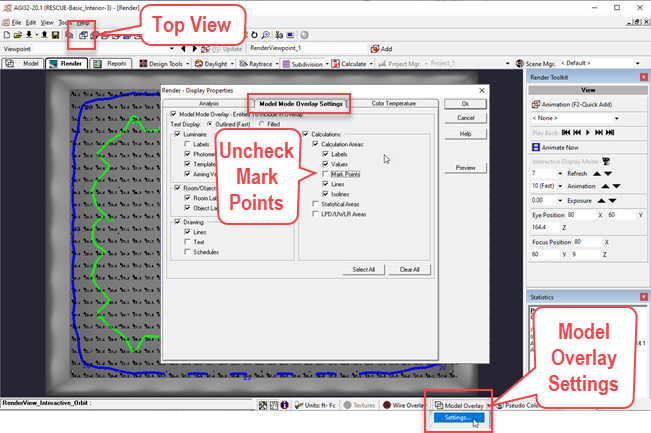
- Select the Top View icon from the toolbar.
- Click on the Model Overlay button (this will superimpose the points and isolines on the view).
- Click on the black arrow next to the Model Overlay button and select Settings.
- Uncheck the box for Mark Points.This is easier to read.
- Click OK to exit the dialog.

AGi32's Anti-aliasing feature is enabled by default when in Render mode. If the view appears not to be anti-aliased, just adjust the view and it will clean it up. This is important in delivering the best quality viewing experience and images when Page Builder captures your views, or you save a rendering using the Export command (File menu). You can adjust the amount of aliasing using the menu. Higher numbers are better and slightly slower.
- Click on the Anti-Aliasing menu (lower right corner of screen) and set to 15.
- Adjust the view to ensure it is applied to the current view.

Now let's save the current view as a Viewpoint.
- On the Viewpoints toolbar, click Add.
This will save the current view along with the Model Overlay properties as “RenderViewpoint_1”. Notice we have elected to use the default viewpoint name.
As soon as you make a change to the current view, the Viewpoints toolbar will show that the viewpoint has changed by placing three Asterisks in front of the viewpoint name (***). You can return the view to the previously saved viewpoint by selecting it from the pull down menu. Or, if you prefer to update the viewpoint, simply click the Update button.

Let's continue and add additional viewpoints.
- Turn off Model Overlay by clicking the button on the bottom toolbar.
- Select the South East Isometric view from the top toolbar.
- Roll the mouse to zoom in a little.
- Now use the Orbit command to gain a view similar to ours below.

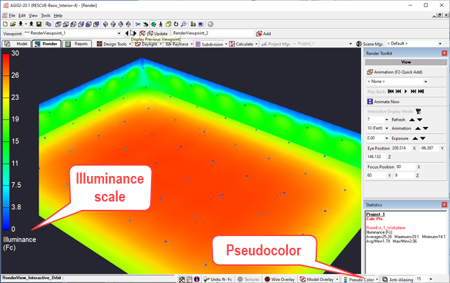
- Enable Pseudocolor by clicking on the toolbar button (to the right of Model Overlay).
Your view may look like ours below, but if it does not, let’s examine the Settings for the Pseudocolor mode.

- Click on the small black arrow attached to the Pseudocolor button and select Settings.
Examine the Settings as follows:
- Select Illuminance.
- Check Apply Maximum.
- Enter 30 fc in the Maximum cell.
- Check Display Scale.
- Verify scale settings of Linear and Auto.
- Click OK to exit the dialog and apply the settings.

Now that your pseudocolor view is set, set a new viewpoint.
- Click Add on the Viewpoints toolbar
You can now move back and forth between your two viewpoints by using the Viewpoint toolbar.
- Try it. Select RenderViewpoint_1.
- Now select RenderViewpoint_2.
Let’s walk into the space and add one more viewpoint.
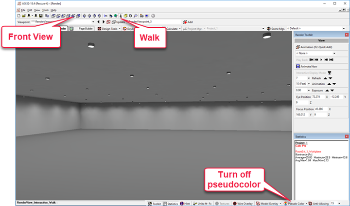
- Select the Front View icon on the toolbar.
- Turn off Pseudocolor.
- Select the Walk command.
- Hold down the left mouse button and move the mouse to walk inward.

When you view looks something like ours, set another viewpoint.
- Click Add the set your third viewpoint.
 RESCUE
Open the file: RESCUE-Basic_Interior-4.agi


